The transmission electron microscope (TEM) operates on many of the same optical principles as the light microscope. The TEM has the added advantage of greater resolution. This increased resolution allows us to study ultrastructure of organelles, viruses and macromolecules. Specially prepared materials samples may also be viewed in the TEM. The light microscope and TEM are commonly used in conjunction with each other to complement a research project.
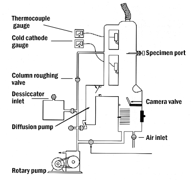
Since electrons are very small and easily deflected by hydrocarbons or gas molecules, it is necessary to use the electron beam in a vacuum environment. A series of pumps are used to accomplish an adequate vacuum for this purpose. Rotary Pumps are the first in the series. They are also called the "roughing pumps" as they are used to initially lower the pressure within the column through which the electron must travel to 10 -3 mm of Hg range. Diffusion Pumps may achieve higher vacuums (in the 10-5 mm Hg range) but must be backed by the rotary pump. The diffusion pump also maintains pressure. In addition a Turbo, Ion, or Cryo Pumps backed by the preceding pumps may be used when an even greater vacuum is required.
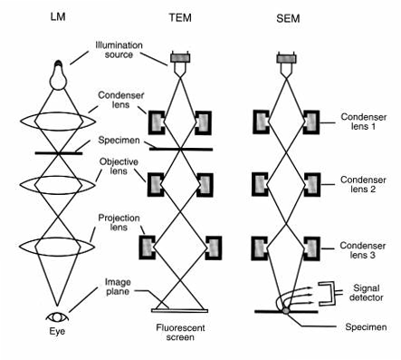
The organization of the transmission electron microscope (TEM) is similar to that of the light microscope.
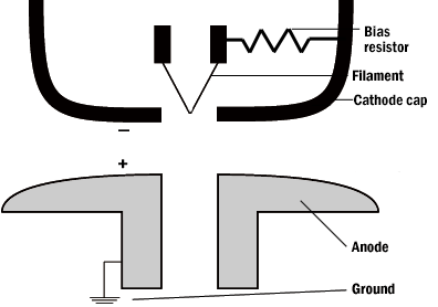
The illumination source (or electron gun) in a thermo-ionic emission TEM works much like a light bulb. A filament (cathode) is the source of electrons. It is usually a hairpin-shaped tungsten wire. An accelerating voltage (fixed amount of negative high voltage) is applied to the surrounding cathode cap. A small emission current is then applied to the filament to achieve the release of electrons. The point at which the gun achieves good thermal emission as well as an acceptable filament life is called the saturation point. The cathode cap ( also called Wehnelt cylinder) must be slightly more negative than the filament. A resister is located in the gun assembly and is controlled by a knob marked "bias". It creates the difference in negative voltage between the filament and the cathode cap. This allows the electrons to collect inside the cap, forming an electron "cloud" . An Anode located below the gun assembly, is electrically at ground, creating a positive attraction for the negatively charged electrons, which overcome the negative repulsion of the cathode cap and accelerate through the small hole in the anode.
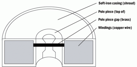
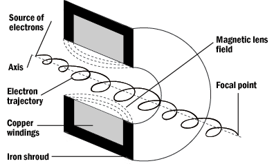
Glass lenses of course, would impede electrons, therefore electron microscope (EM) lenses are electromagnetic converging lenses. A tightly wound wrapping of copper wire makes up the magnetic field that is the essence of the lens. Surrounding these coils is a shroud made of a metal that will not hold a magnetic charge when the lens is shut off. The electron moves through the center hole in this solenoid. The electron path is further constricted by a brass lining inside this space known as the pole piece. The pole piece has a small gap within it at which point the beam is most influenced by the electromagnetic current. This is appropriately referred to as the pole piece gap.
Electron paths are usually represented by straight lines running through a convex lens. More accurately, however, the electron paths form a tight spiral as they are accelerated through the lenses. The path and trajectory taken by the electrons are influenced by the lens current as they pass though a small opening in the lens.
Cross over is the point at which the electrons converge. This defines the local length of the lens.
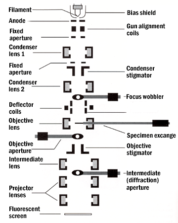
The condenser lenses in the TEM serve much the same function as that of the condenser in the light microscope. They gather the electrons of the first crossover image and focus them onto the specimen to illuminate only the area being examined. A condenser aperture is used to reduce spherical aberration. The Objective lens is used primarily to focus and initially magnify the image. The specimen stage is inserted into the objective lens for imaging purposes. A cold finger or anticontaminator also sits near the objective lens. It consists of a thin copper rod at liquid nitrogen temperatures, so that contaminants are attracted to it. The cold finger reservoir must be must be filled with liquid nitrogen before the microscope is used. Contaminants sometimes cause a phenomenon known as drift. Drift is the apparent "movement" of the specimen across the screen. It is caused by poor contact between the grid and the specimen holder causing a buildup of heat and static charges. An objective aperture is used to enhance specimen contrast. Intermediate lenses magnify the image coming from the objective lens. Finally, projector lenses further magnify the image coming from the intermediate lens and projects it on to the phosphorescent screen.
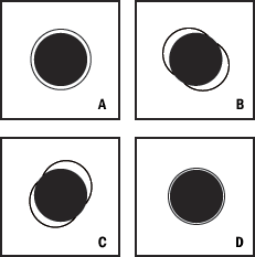
To optimize imaging in the TEM a beam alignment should be performed prior to use. A tool for this alignment is a holey grid. A holey grid is a TEM grid support coated with a thin plastic film and a stabilizing carbon layer. It is manufactured to contain small round holes useful in alignment of the TEM. The holes in the grid create Fresnel fringes when the electron beam diffracts around the edges as the electrons come together at overfocus. The edge of the hole appears to have bands or fringes.
The final image is viewed by projection onto a phosphorescent screen which gives off photons when irradiated by the electron beam. A film camera is located beneath the phosphorescent screen. The screen is raised in order to expose a special photographic film with a thicker emulsion layer than light film. An alternative to photographic film is digital capture with a computer digitizing and archiving (CCD) camera.
The operator is responsible for adjusting variable bias, recognition of aberrations, image drift, photography, specimen contrast, resolution, even illumination, and filling the anticontaminators with liquid nitrogen before using the TEM.
Instrument maintenance that requires staff or company repair are filament saturation, filament exchange, aperture cleaning or replacement, specimen holder cleaning, vacuum pump maintenance, and viewing screen.
The theoretical resolution described by Abbe for the light microscope can be modified and applied to the TEM by using DeBroglie's formula. DeBroglie stated that the wavelength of an electron beam is a function of the accelerating voltage used. By increasing the accelerating voltage, a shorter wavelength is obtained. The shorter wavelength is applied to Abbe's equation and the increased resolution can be calculated. Typical accelerating voltages for a biological TEM range up to 125,000 Volts.
Abbe's equation: d = 0.753/aV1/2
sin a
d = resolution in nm
a = half aperture angle
V = accelerating velocity
Resolution is defined as the distance at which two points or objects can be distinguished. Therefore as r approaches zero we say that the resolution is increased.
DeBroglie's formula:
l = h/mv
h = Plank's constant
(6.626 x 10 –23 ergs/ sec)
m = mass of the electron
v = electron velocity
DeBroglie's formula states that if the accelerating voltage is increased, electron velocity will increase as will resolution.
As in the light microscope several factors detract from this number. Spherical aberration is also present in the TEM as electrons passing through the periphery of the lens are refracted more than those passing along the axis. All the electrons will therefore not reach a common focal point. To reduce spherical aberration, an aperture is used to eliminate some of the periphery electrons.
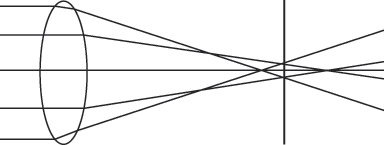
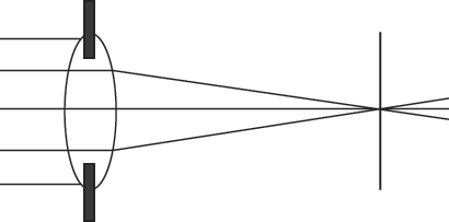
a. b.
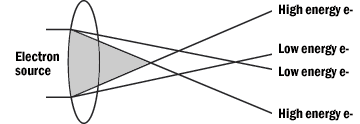
One would not normally expect chromatic aberration to be a problem in an electron microscope, but, electromagnetic radiation of different energies converge at different focal planes. This is essentially the same problem as the chromatic aberration observed in the light microscope. To correct for chromatic aberration, increase accelerating voltage, improve the vacuum and/or use a thinner specimen.
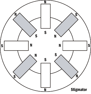
An astigmation occurs when a lens field is not symmetrical in strength, but weaker in one plane than another. Astigmation can be caused by imperfect polepiece boring, non-homogenous blending of polepiece materials, or by dirt on the polepieces, apertures, and/or specimen holders. A stigmator can be used to apply a correcting field of the appropriate strength in the proper direction to counteract the asymmetry. Stigmators are located in the objective and condenser lenses.
Although diffraction can be useful, diffraction of electron waves around the aperture openings can interfere with the initial wave front. The results are an unclear or out-of-focused image. It is important to create a balance between reduction of spherical aberration and diffraction by selecting an appropriate sized aperture.
Image formation in the electron microscope is achieved by electron scattering. The interaction between the primary electron beam and sample results in a change of energy and/or trajectory without altering its kinetic energy. Backscattered electrons are an example of elastic scattering. Inelastic scattering occurs when an electron transfers some kinetic energy of the atoms of the sample. Examples of inelastic scattering are secondary electrons, auger electrons, and transmitted electrons.
Definitions
Accelerating voltage-The fixed amount of high voltage applied to the cathode cap of the transmission electron microscope.
Anode-Located below the gun assembly, the anode is at ground with a small aperture for electrons to move through. This aperture serves as the first lens encountered by the electron.
Astigmation-An aberration caused by uneven electrical fields surrounding a lens.
Cathode-The filament or source of the primary electron beam. Cathode Cap-(also called Wehnelt cylinder) surrounds the gun assembly. The high voltage is applied here.
Cold finger-A long copper rod extending along the inside of the electron column. When its reservoir is kept filled with liquid nitrogen, the rod attracts contaminants that might otherwise degrade the chamber's vacuum.
Condenser aperture-A small laser-bored hole in a flat strip of molybdenum placed near the condenser lens that helps to limit spherical aberration.
Condenser lens-The first electromagnetic lens that the electron beam encounters. Focuses the electrons onto the specimen.
Chromatic aberration-Electromagnetic radiation of different energies converging at different focal planes.
Crossover-The point at which the electrons converge. The smallest visual beam image on the phosphorous screen.
DeBroglie's formula-The wavelength of an electron is a function of the accelerating voltage used.
Diffusion pump-The second pump in series in the evacuation of the TEM column.
Drift-The apparent "movement" of a specimen across the field of view.
Elastic scattering-Electron scattering where little kinetic energy is lost, but the trajectory of the electron is substantially changed.
Electron scattering-The displacement of an electron beam by a sample, causing formation of an image.
Emission current-A small amount of heat added to the electron source in order to release electrons through the column.
Fresnel fringe-A diffraction pattern formed around a small hole when the beam is over-focused onto it.
Holey grid-A thin support film manufactured to have holes so that it may be used to align a TEM.
Inelastic scattering-Scattering of electrons in which the electron loses kinetic energy, but changes trajectory only minimally.
Intermediate lens-Help the objective lenses to magnify the specimen.
Objective aperture-A small laser-bored hole in a flat strip of molybdenum placed near the objective lens. Adjustment of this aperture strip can aid in adjustment of contrast of the image.
Objective lens-The main magnifying lens.
Phosphorescent screen-The screen at the bottom of the electron column, where the specimen is viewed.
Pole piece-A brass fitting inside an electromagnetic lens to assist in narrowing the primary electron beam.
Projector lens-The final lens in a TEM. Used to assist in magnifying the image and to project the magnified image onto the phosphorus screen.
Rotary pump-Also called the roughing pump. The first pump in the vacuum pump series.
Saturation Point-The point at which good electron emission from the gun is achieved without shortening the filament life appreciably.
Shroud-The soft iron casing surrounding the electromagnetic lenses of the TEM. Solenoid-An electromagnetic lens fashioned by copper windings with a direct current running through it.
Specimen stage-The platform on which a specimen sits while being imaged.
Spherical aberration-Electrons passing through the periphery of a lens are refracted more than those passing through the center of a lens. The electrons, therefore do not reach a common focal point. Improved with the addition of an aperture.


