Breadcrumb
- Home
- Methodology
- Light Microscopy
Light Microscopy
Main navigation
Introduction
Light microscopes play an important role in many research laboratories, including electron microscopy facilities. They can be used as a primary visualization tool or in support of electron microscopy. Samples for light microscopy are prepared in an ever-increasing number of techniques, and can range from sliced biological organisms and tissue cultures to materials science and geological samples. Light and electron microscopes share many similarities in their optical principles. Understanding how a light microscope works is not only critical for obtaining optimum light images, but also for understanding electron microscopy.
Principles of Light, Electrons, & Microscopy
In microscopy we take advantage of waveform properties of light. These waves when produced at a particular source vibrate at right angles to the line of propagation. Each wave has a peak and trough. The distance traveled forward by the light ray is one wavelength (lambda). Wavelength varies with the color and intensity of the source.

Figure 1: Schematic diagram of a wave.
How the image is formed
The structures the light microscope is called upon to resolve exert only a small influence on the light they transmit. What is changed is the phase of momentary vibration. Conventional brightfield illumination will lack contrast and the details of the sample remain invisible. When the emerging waves have acquired a larger phase difference due to changes in refractive index, greater contrast is produced. This manifests itself by an edge effect (diffraction, refraction, and reflection). Sample details may be resolved in a number of ways. When a light passes through stained structures intensity is reduced selectively depending on the color and density of the sample as the light is absorbed. Selective absorption of wavelengths of white light produces colored light. Refraction changes the direction of a light ray as it passes from one medium to another. The shorter the wavelength, the greater the refractive angle. Diffraction is the bending of light rays around objects with sharp edges. A new wave front is created at this edge. Diffraction can be useful, but can also reduce resolution. When light is dispersed it is separated into its constituent wavelengths as a result of refraction on entering a transparent medium. Contrast can be defined as a steep slope between bright and dark image points. Adequate contrast MUST be achieved before the specimen can be resolved.
Two terms that are often confused, but are central to microscopy are magnification and resolution. Magnification is the degree by which dimensions in an image are, or appear to be, enlarged with respect to the corresponding dimensions in the object. Resolution is the act or result of displaying fine detail in an image. Magnification without resolution would be meaningless.
The theoretical resolution of the light microscope was first defined by Abbe in the following equation.
Abbe's equation for theoretical resolution of the light microscope:
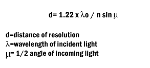
The actual resolution achievable with a light microscope is not as great. We will discuss the reasons for this later.
It is important to understand and to recognize the various components of the light microscope. The first and perhaps the most important element are the lenses.
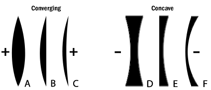
Figure 2: The six simple lenses. A, B, & C are converging or positive lenses. D, E, & F are concave or negative lenses.
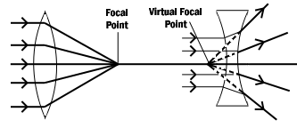
Figure 3: Converging and diverging lenses. Parallel rays enter a convex lens converge and meet at the principle focus. The distance between the center of the lens and the principal focus is the focal length. Parallel rays entering a concave lens diverge and never meet.
The Objective Lens is the first part of the imaging system; the objective lens forms a primary, enlarged image of the object. Very fine details are distinguished with the objective lens. The eyepiece sometimes called the ocular lens, is the second lens, which forms a secondary, further enlarged image. By multiplying the magnifying power of the objective lens and the magnifying power of the ocular the final magnification is found. A Substage Condenser lens is the third optical component. It is placed on a platform beneath the object. Light is directed through the substage condenser and converges to a point at the position of the specimen. The light rays diverge as they pass through the specimen and form an inverted cone, whose base is just large enough to fill the aperture of the objective. The size of the light beam is controlled by a diaphragm beneath the condenser called the aperture diaphragm.
The light source should contain both a lens to project an image of the lamp filament called a field condenser and a diaphragm to control the size of the illuminated field called a field diaphragm.
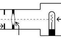
Figure 4: Typical lamp for light microscope.
Kohler Illumination is the most common method of illumination. In Kohler illumination the image of the source is projected by the field condenser onto the substage condenser, to the top of the plane of the object. This method assures even illumination.
Modern light microscopes use several different modes of operation depending on the needs of the investigator. The most common of these being brightfield microscopy in which direct light passes through the objective aperture and illuminates the background against which the image is seen. Since the structural elements being resolved have little variance in refractive index, the image will lack contrast and the details remain invisible. Small structure detail can be revealed by changing the absorption of the object by means of staining.
Many microscopes have special lenses that allow an investigator to image using phase-contrast. This method reveals details in specimens possessing very slight differences in optical path or refractive index in the surrounding media. Phase contrast requires no staining and can be used with living tissue. Contrast is produced in this method by phase differences in the light leaving the object to amplitude differences in the image. A phase plate alters the optical path length traveled by diffracted light from that traveled by direct light.
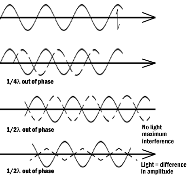
Figure 5: Light waves in brightfield and phase contrast after passing through an object. Pathway A represents the lightwave before encountering the object. Wave B represents the wave phase after passage in brightfield (unstained mode). C compares the wave phase of an object veiwed with phase contrast.
Differential interference contrast (DIC) differs from phase contrast in that the image has a strong relief and three-dimensional appearance. It must be remembered that the impression of surface details are the results of the optics and not the specimen for most biological samples. The optics for DIC consist of a polarizer at the light source and Wollaston prisms in the condenser and above the objectives. The beam passes through the polarizer, enters the first prism where it is split in two. One beam vibration is parallel to the prism and one is perpendicular. Both beams pass through the specimen in parallel in close proximity and are recombined in the second prism.
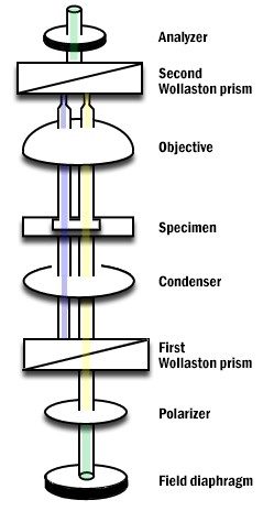
Figure 6: Differential Interference Contrast Schematic.
Darkfield microscopy is a mode in which direct light is prevented from passing through the objective aperture, but a hollow cone of light forms an apex in the plane of the specimen. The image is formed by light scattering from features of the object. Details appear bright white against a dark background. Darkfield can also be used for living bacteria, algae and plankton.
Some materials produce light when excited by short wavelengths of radiation. This effect is called fluorescence or auto-fluorescence. Specimens that do not fluoresce by themselves may be treated with fluorochromes which produce a secondary florescence. By illuminating with a high intensity mercury or xenon source and filtering out all but the desired excitation wave length to contact the specimen, the resulting longer (less energetic) wavelengths of emission from the specimen its self veiwed. Fluorescence microscopy can be used to enhance particular organelles, immunocytochemistry, in-situ hybridization, enzyme cytochemistry and elemental localization.
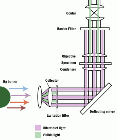
Figure 7: Fluoresence microscope.
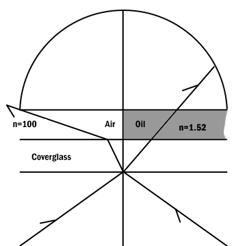
Figure 8: Comparison of a dry and an oil immersion objective.
Abbe in order to ease in identification of lens quality devised an equation for numerical aperture. Numerical aperture numbers can assist in comparing angles of dry, water immersion, and oil immersion objectives. Note the similarity to Abbe’s equation for theoretical resolution. This number is found on all objective lenses.
N.A. = n sin u
n = refractive index of medium
u = 1/2 the angle of light rays taken in when focused on the object.
When choosing an objective another consideration is depth of field. Depth of field is the distance from the nearest part of the subject in acceptable focus to the farthest part of the subject in acceptable focus. The efficiency (resolution) of a lens is inversely proportional to the depth of field (Table 1).
| N.A. | .25 .30 .50 .65 .85 .95 |
| Depth (in microns) | 8.0 5.5 2.0 1.0 .25 .10 |
Table 1: Variation in Depth of Field with Change in N.A.
Two aberrations within lenses detract from Abbe's equation of theoretical resolution. These aberrations are called spherical aberration and chromatic aberration. Spherical Aberration occurs when outer rays entering a lens are diffracted differently from those entering near the center. A solution for reducing spherical aberration is introducing a diaphragm or aperture.
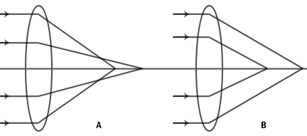
Figure 9: Spherical aberration of a simple lens. A. Under correction. B. Over correction.
The thickness of the cover glass should be chosen according to specifications of a particular objective. Deviation from the required thickness results in over correction or under correction of spherical aberration.
Chromatic Aberration occurs as white light entering a lens is broken into a spectrum from red to violet. Violet rays (more energetic) are refracted more than the red rays (less energetic). Consequently an uncorrected lens will be surrounded by color fringes. The more expensive lenses have a higher degree of correction.
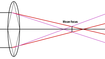
Figure 10: Chromatic aberration of a simple lens. Each spectrum color has a separate focus.
Definitions
Abbe's equation- Theoretical resolution of the light microscope.
Absorption- Light reduced selectively depending on color and density of the medium it passes through.
Brightfield microscopy- Light passes directly through the specimen and usually requires staining.
Chromatic Aberration- Caused by light waves of different energies passing through a lens.
Condenser Lens- Focuses the beam onto the specimen
Contrast- The slope between white and black. More slope, more contrast.
Converging lens- Refraction of light to a focal point on the opposite side of the lens.
Darkfield microscopy- Direct light is prevented from passing through a specimen, but a hollow cone of light is alloweed to form an apex in the specimen plane resulting in a bright specimen in a dark background.
Depth of field- The distance between the nearest to farthest points on a sample that are in acceptable focus.
Differential interference contrast- The mode of operation which gives the most relief in an unstained sample.
Diffraction- Bending light rays around objects.
Dispersion- Separation of light into its constituent wavelengths.
Diverging lens- Refraction of light outward by a lens from a focal point on the same side of the lens as the illuminating light.
Fluorescence microscopy- Samples produce light when excited by short wavelengths of radiation.
Field aperature- An adjustable diaphragm placed near the condenser lens to help direct light to the specimen.
Kohler illumination- A mechanism of alignment used to optimize even illumination of a specimen.
Magnification- The degree by which dimensions in an image are or appear to be enlarged with respect to the corresponding dimensions in the object.
Objective lens- The primary lens for image magnification.
Phase contrast microscopy- Reveals details in specimens by changing wavelengths phases in the light path.
Resolution- The act or result of displaying fine detail in an image.
Refraction- The change in direction of light rays as it passes from one medium to another.
Spherical aberrations- Outer rays entering a lens are refracted differently than rays passing through the center of the lens.
Wavelength- Distance traveled by a light ray from peak to peak or trough to trough.